If you are a technician, don’t miss this Ring Tester on your repair bench. It is rare to find Linear Power Supply on our equipment today because everything was made with SMPS today. SMPS or Switch Mode Power Supply offers an efficiency and more light than Linear Power Supply with the same performance. It is hard to find a big bulky transformer today on our consumer electronic equipments today because everything were dominated by Switch Mode Power Supply.
The disadvantage about power supply which are difficult to troubleshoot because it’s complexity. We need a reliable tool to help us troubleshoot SMPS. You can’t depend on just one test equipment to repair SMPS, that is a hard job. I’ve found this tester really helped me to do a troubleshooting job. I would never do a repair job without this one because it helped me much.
I build this tester based on Blue Ring Tester schematic from Anatek Corporation manual. See below picture.
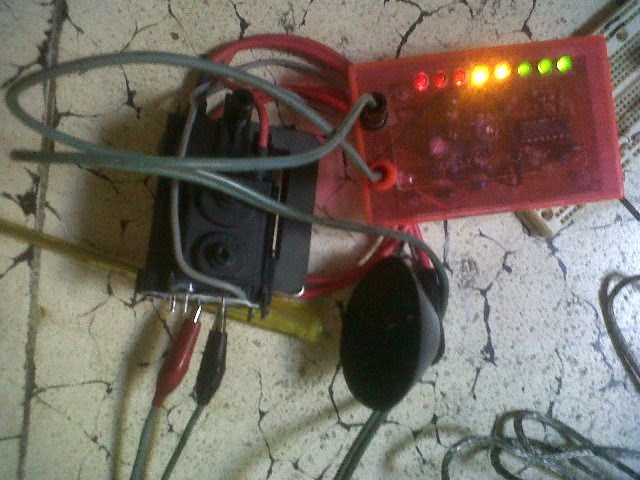
You can see I have tested one flyback which is shorted. The faulty fyback wouldn’t make Ring Tester led lit. It is just one or two led were lit if your flyback faulty, when you have a heavy shorted on your flyback, the led on Ring Tester wouldn’t lit at all. This is my Ring Tester when test a bad flyback.
This below picture when I test good flyback
You can see all led on the Ring Tester is lit. This is a sign for good flyback. Hold on, you must be surprised if you know what else this tester could do. What it is? SMPS Transformer of course!
Did you ever find the faulty SMPS Transformer before? I have found several SMPS Transformer were shorted and I am wondering what if I don’t have this good equipment. Just build or buy it if you have a budget.
You can find information on the internet. It is really worth your time and your money on this equipment. You can test SMPS transformer primaries with this Ring Tester. You would see the difference from good and bad SMPS transformer, you just need a little time to find your transformer was failed.
You can find information on the internet. It is really worth your time and your money on this equipment. You can test SMPS transformer primaries with this Ring Tester. You would see the difference from good and bad SMPS transformer, you just need a little time to find your transformer was failed.
As professional technician, you have to do troubleshooting job faster. If you could repair one equipment in the shortest time a day, it means you can repair more equipment on a day !
I am not salesman from Anatek Corporation or elsewhere. I just found this tester really do his job well. I remember one day where I don’t have this tester yet. It was really hard to find the causes from dead TV. I am wondering is SMPS section or high voltage section (horizontal section) were defective. I have tested primary and secondary section, but I couldn’t find the culprit. I waste my time almost two hours to find the culprit and that is non profitable for a technician.
Don't forget to see my DIY ESR Meter design too


Hi, so great to see another enthusiast with the same idea!
ReplyDeleteI have just finished building my DIY tester and it seems to work. However, I don't get the one flickering red LED when the device is not connected to any coil. The original Anatek tester does that.
By reducing C8 to 100pF I got one solid red LED at least. Studying the clock and reset signals to the 4015 chip with a scope, I cannot imagine how a flickering could possibly work.
How does your DIY tester behave?
Hi Hermann, This DIY Ring tester don't have flickering red led like Anatek tester does. it just lit as usual led. Mine was same like your one too. sorry for very late reply...
ReplyDeleteI'd love to build one of these, as I have a real need for one, could you tell me what chips you used.
ReplyDeletePaul
I build it with 2 ic which are LM394 dual comparator and CD4015 dual 4bit shift register.. :)
ReplyDeleteSorry i mean LM393.. Thank you :)
ReplyDeleteThe circuit diagram you have shown is for the upgraded ring tester using 4069 IC instead of LM393. Do you know how I could get the pcb design of the upgraded ring tester.
ReplyDeleteBala.